blinky++, Part 1 - An LED μC project Taken Too Far
Build Timeline
I’ve had this project on my plate for a while. Saying this project has grown with me as I’ve learned about hardware development would be one way to put it, but calling it scope creep and project abandonment wouldn’t be lying either.
- 2013: Found a schematic on Instructables and ordered components. Verified function of a single shift register breadboarded with LEDs and an Arduino. Stored the project safely away in a shoebox for a few years.
- 2017: Soldered the LED cube. Soldered all components to a piece of perfboard. The design didn’t work - the LEDs would only intermittently turn on, and they would flicker when they did. The project returned to its shoebox.
- 2019: Investigated the issue again. Still had the same intermittent behavior. I found that the LEDs worked when only a single LED from each shift register was lit, but that they started to flicker once more were lit. Started to read the datasheet for the shift register and found that it had a maximum of 50mA output for all outputs combined. The shift register was intended for logic, not power, so I spec’d out a new shift register. The project found a home in its shoebox again.
- 2021: Entered the schematic in KiCad, layed out a PCB, and ordered.
Theory of Operation
I copied the theory of operation from a couple of old Instructables guides back in the early-2010s, when this was a popular project doing the rounds on maker YouTube channels and blogs.
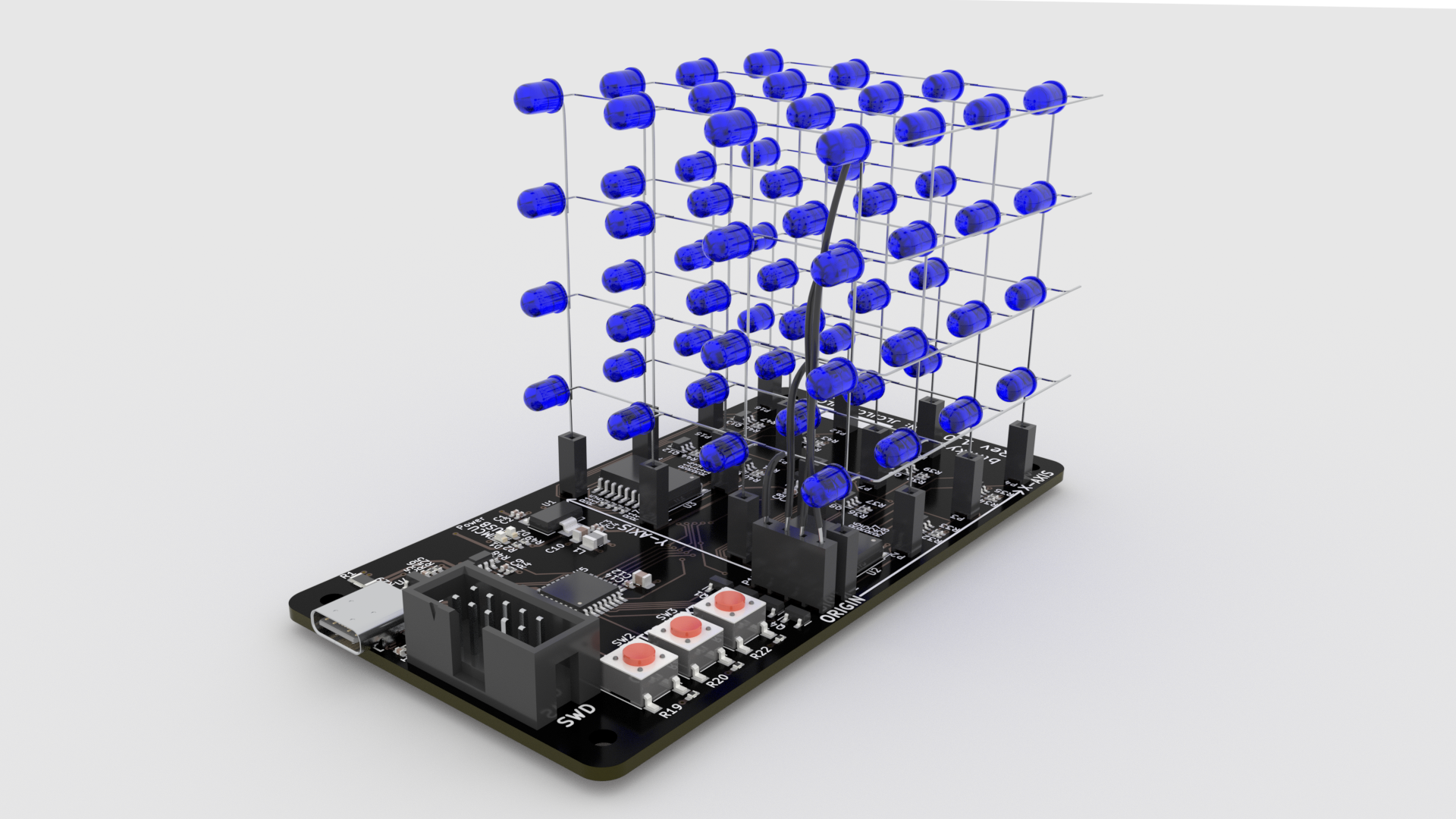
In order to individually control 64 LEDs, this project heavily utilizes multiplexing. The anodes of each LED are wired together in vertical columns, and the cathodes are wired together in horizontal layers. The anodes are controlled with daisy-chained TPIC6595’s, which are shift registers that can source 250mA per output. This configuration requires only 9 GPIO pins to control all 64 LEDs.
There are drawbacks to this configuration - since the anodes are wired together in vertical columns, not all LEDs can be enabled at once and controlled individually. This is circumvented by using persistence of vision, which allows us to rapidly switch between layers, similar to scan lines in an NTSC signal. If we do this faster than the refresh rate of the human eye, we can create the illusion that all rows are being enabled at the same time.
The New Design
The 2021 point on the timeline marked spinning a new PCB for the design.
Requirements
Cost:
- 2-layer board
- Less than 100x100mm (most budget PCB fabs have a significant price jump for dimensions larger than this)
Functionality:
- Meets Theory of Operation above
- USB-C for power and communications (except flashing)
- Set current limit based on CC1 and CC2 voltage (not USB PD)
- Headers to allow for removal of the LED cube
- 30mA per LED
- Buttons to change displayed LED patterns
- Adjustable brightness (per-LED brightness not required)
- Limit brightness based on USB current limit above
The Result
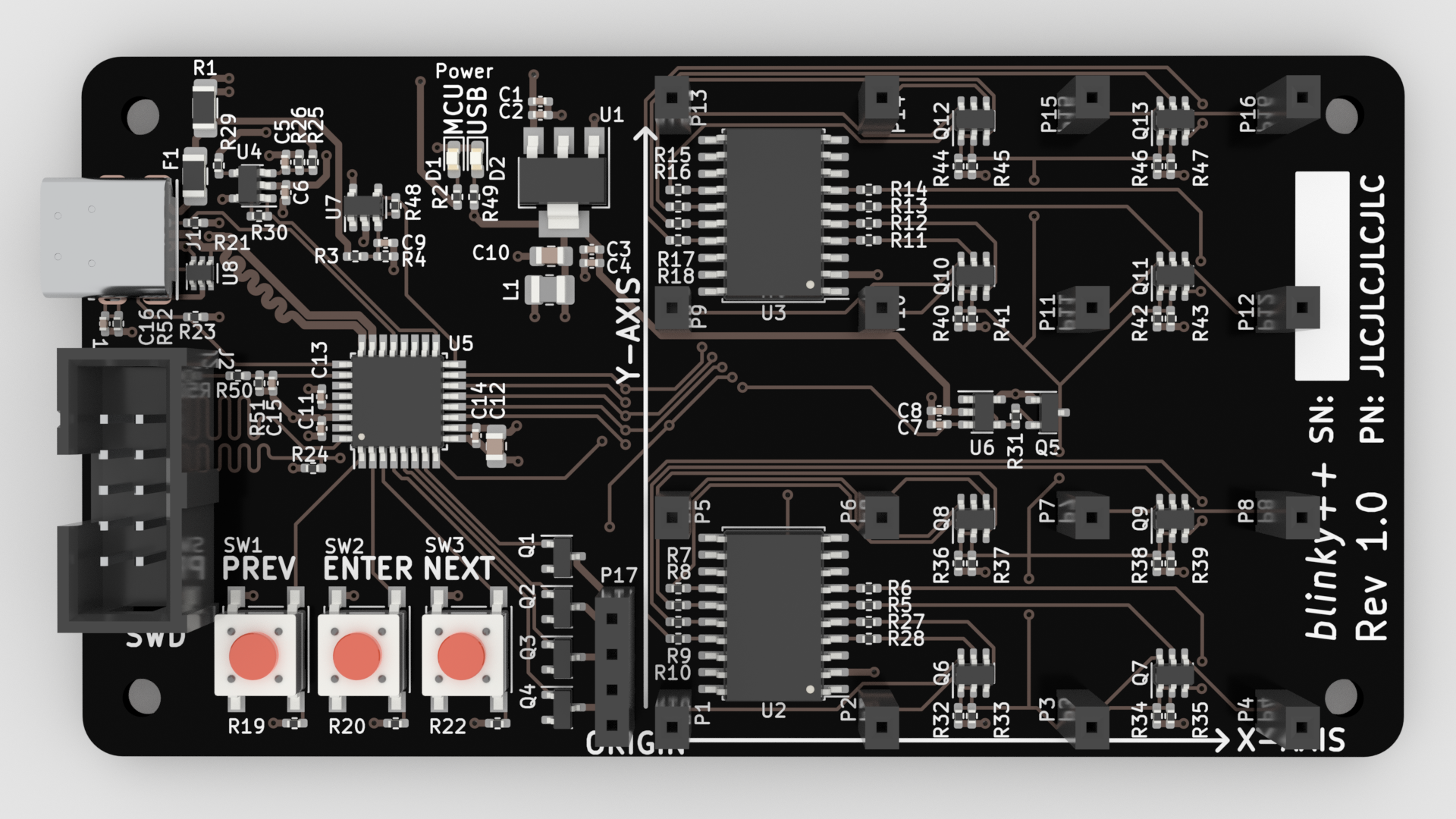
Very similar in concept to the old perfboard design, except for 3 major differences:
- Integrated microcontroller (SAM D21, a Cortex-M0+ based MCU).
- Voltage-controlled constant current sources for the LEDs.
- Properly spec’d shift registers.
Closing Thoughts
Just like the title says, this is an LED MCU project taken too far - it’s overcomplicated and largely untested, and I’m sure I’ll run into issues during bring-up. But, the real point of this project was to learn more about microcontroller-based designs, analog designs, and USB-C, and I think it’s already done a great job of that.
The design files are available on my GitHub: amakovec/ledcube, including the KiCAD symbols and LTSpice sims.
In Part 2, I’ll cover board bring-up and any issues I encounter there.